


For the camera to accurately assist the laser cutting machine in positioning and operation, 3 step operations are required.
- Camera lens calibration
- Camera alignment calibration
- Camera application
Please read the following camera connection tutorial and connect the camera.
Camera lens calibration
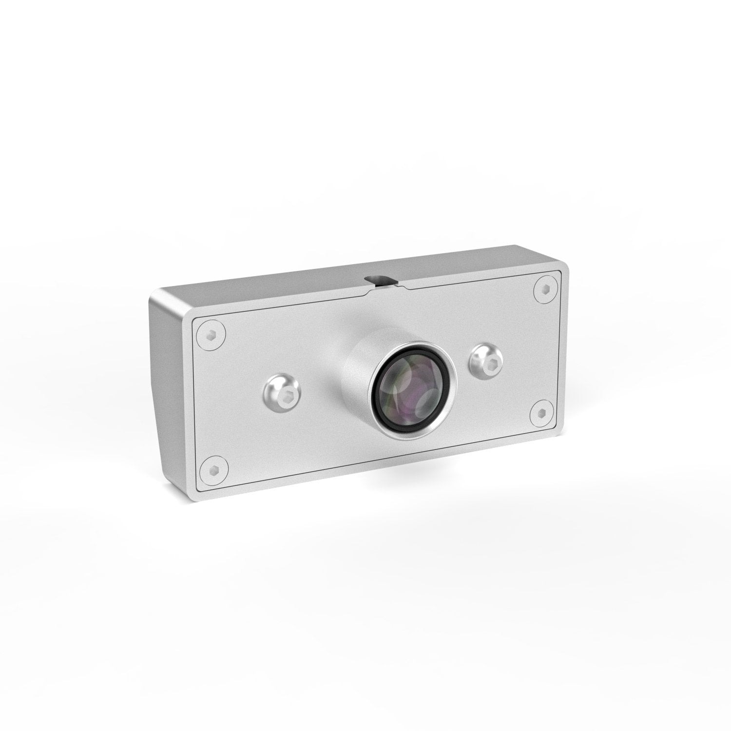
The lens type of TOOCAA Smart Camera for L2 is a fisheye lens. To effectively use this type of fisheye lens, it is necessary to calibrate the lens to ensure that it does not distort when capturing images.
Camera Model Selection
Connect the laser cutter and camera to your computer with a USB cable, start LightBurn, and click the Calibrate Camera Lens option.

Click on the Calibrate Camera Lens option
Select the camera model. Select Fisheye Lens and 5MP-60, and click Next.
5MP-60 means the camera has a resolution of 5 megapixels and can record video at 60 frames per second. Just select the corresponding parameters in LightBurn.

Select the camera model, fisheye lens, and 5MP-60
Click the Align Camera option to start camera alignment calibration.

Click on the Align Camera
TIPS: If you click other options by mistake, you can start camera alignment calibration through LightBurn Tools→Camera Alignment Calibration.

Click on camera alignment and calibration
Camera alignment calibration
Select the connection mode
In the Connection Mode window, select the mode where the camera is located on top of the laser cutter (option 1 on the left).

Select the connection mode
Test image generation
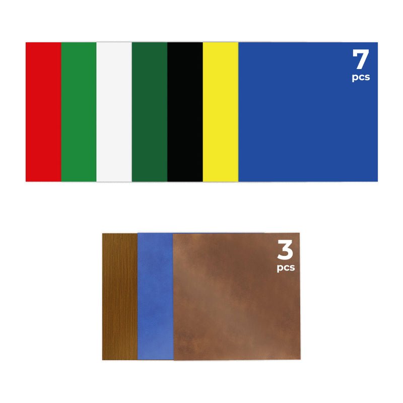
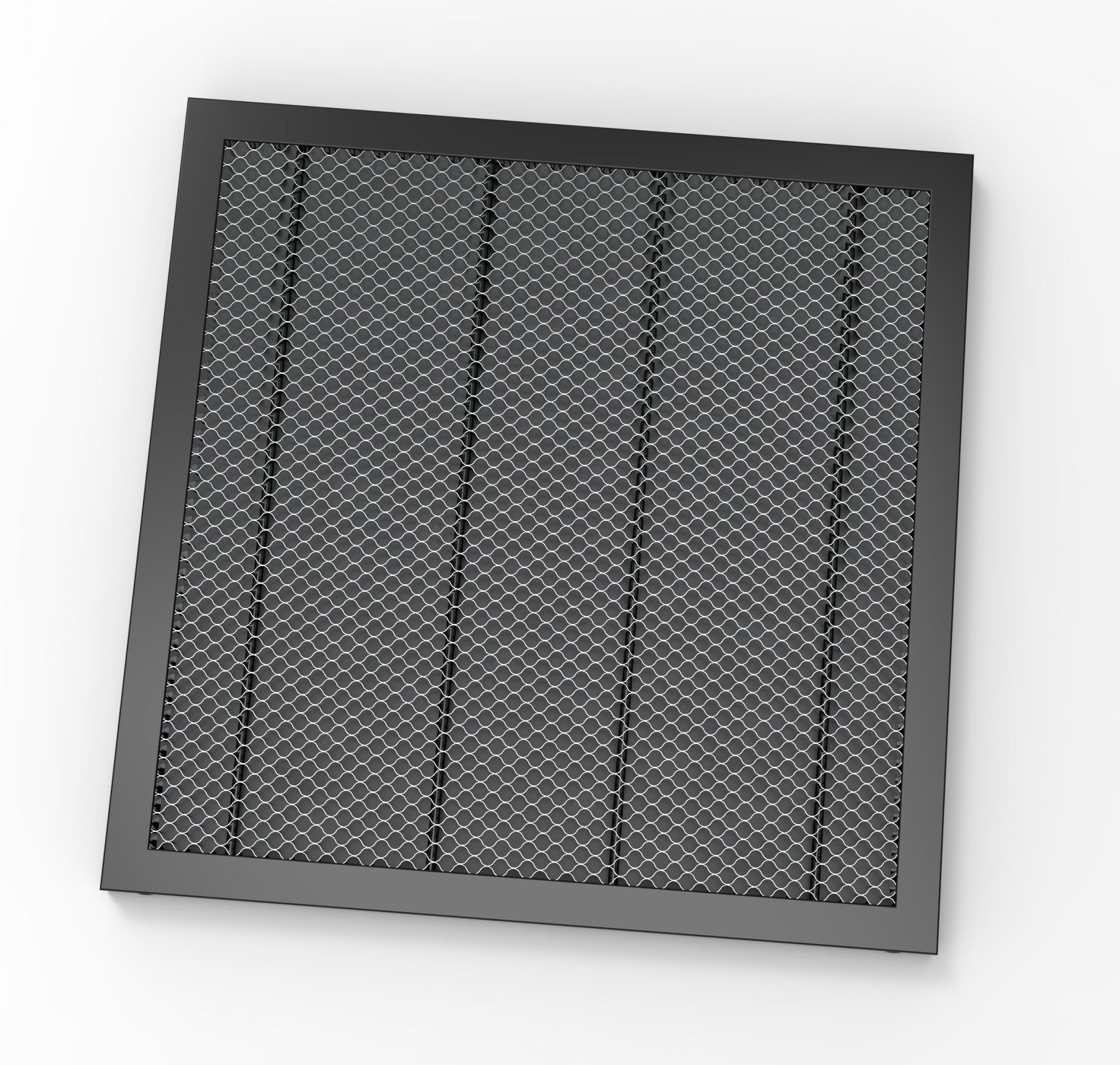
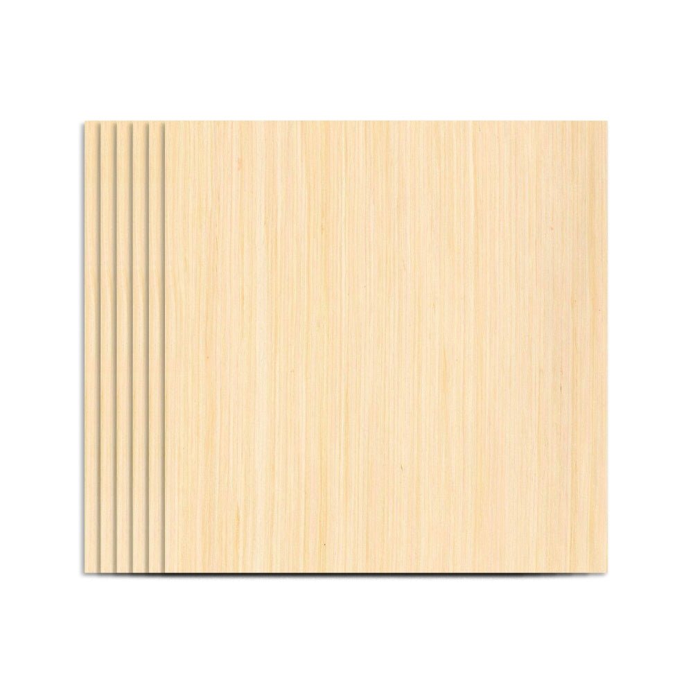
Prepare 400*400 paper or other material for test image generation. Lay the material flat on the bottom of the laser cutting machine, and adjust the corresponding parameters according to the selected material thickness. Select the engraving parameters of the appropriate material, click the Frame button to test, and then click to start engraving the test image. Click Next when the test image is engraved.
Note: The parameters shown in the figure are for reference only. Please set the corresponding parameters according to the material and thickness of the actual test material!

Test image generation steps
Note: If an alarm sounds, check whether the laser head has been reset. If the alarm still sounds after resetting, adjust it appropriately to reduce the proportion.

Adjust it appropriately to reduce the proportion
Image location capture and marking
Capture the generated test image. Proceed to the next step after the capture is completed.
Note: The captured image should be the same as the preview perspective. If the image captured is a fisheye view, please return to the lens calibration step and re-calibrate the lens.

Image Capture
Use the mouse to mark and confirm the 4 positions on the test image in the order of numbers shown.

Mark and confirmed the location point
Note: Please ensure to click the mouse accurately at the circle center.

Zoom in with the mouse to mark the location
TIPS: You can move the mouse, zoom in and out to test the image, and then accurately click the circle center at 4 locations.
After the 4 locations are accurately marked one by one, click Finish.

Click Finish
Camera Application
Camera control window Overlay preview
Click Window→Camera Control to open the Camera Control window.

Select the camera control window
Click Update Overlay and your calibration is complete!

Click Update Overlay

Update the overlay status display
TIPS: After adjusting the position of the material to be cut inside the laser-cutting machine, there is no need to recalibrate the camera, click Update Overlay.
If the preview position is offset from the actual position, you can adjust the X and Y axes in the Camera Control Panel.

X-axis and Y-axis adjustment
Practical operation and application of camera
Place the cutting materials into the laser cutter and click "Update Overlay".
In the LightBurn overlay view, you can design the engraving and cutting of the material according to the target position.

Design Reference
Note: Each time before using the camera, you need to perform a device connection and a two-step (Camera lens calibration and Camera alignment calibration) camera calibration operation.
Camera connection tutorial website
Camera usage tutorial website: https://docs.lightburnsoftware.com/legacy/Camera/
Camera usage tutorial video website: https://www.youtube.com/watch?v=ONnmCaoUkLQ