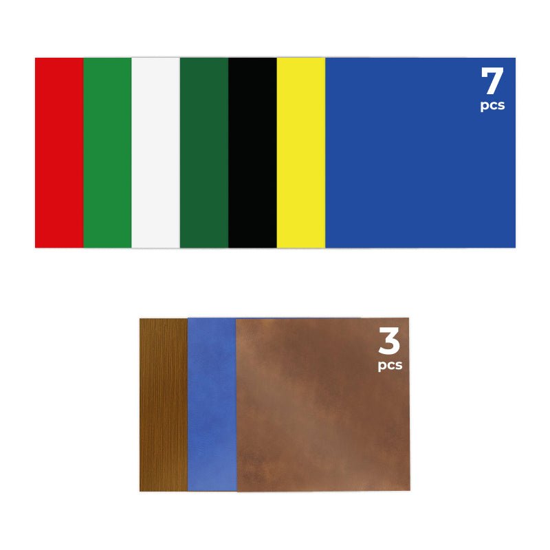

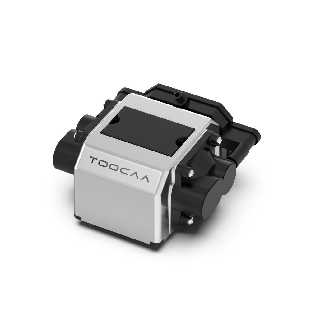

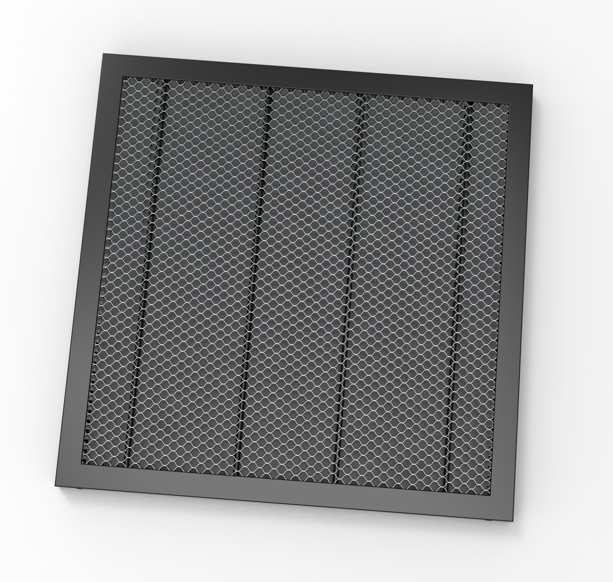


Unboxing inspection

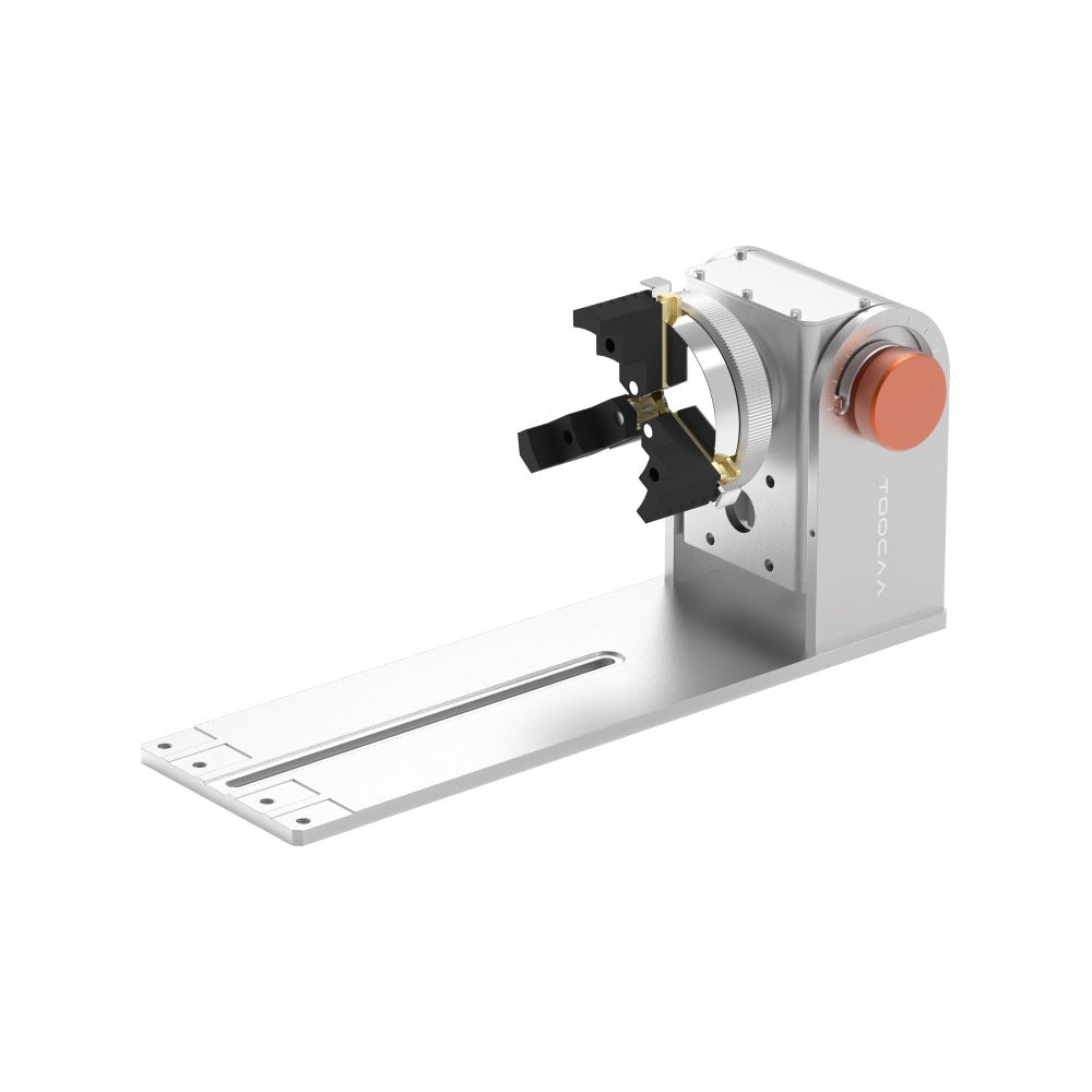
Roller Rotary Accessories Operation Tutorial
1. Insert the clutch components into the chuck body assembly and secure it with the screws.

Fasten clutch components
- TIPS: Adjust the interface angle by twisting the knob of the rotating accessory can for easy alignment and proper insertion of the clutch components.

2. Measure the diameter of the material being cut with a vernier caliper or tape measure and select the appropriate clutch components based on the diameter of the material being cut/engraved.

Size types for applicable roller rotary accessories.
3. Insert the roller assembly into the clutch components along the gap at the bottom of the chuck body assembly.
- TIPS: By twisting the knob on the chuck body assembly of the rotating accessory to adjust the interface angle inside the clutch components, the roller assembly can be easily aligned and correctly inserted.

Roller assembly insertion
- NOTE: The screw holes at the rear of the roller assembly should be aligned perfectly with the screw holes on the chuck body assembly of the swivel attachment to be properly connected.

Roller assembly connection check
4. Secure the roller assembly with screws.

Fasten roller assembly
- Note: Please rotate and move the roller assembly in a small range after fixing it to ensure that the roller assembly can be used normally. If it is loose, it means that the roller assembly has not been installed properly. Please remove the roller assembly and recalibrate and install it.

Roller assembly test
Chuck Rotary Accessories Operation Tutorial
1. As shown in the figure. Adjust the chuck knob clockwise to unlock, and adjust the chuck knob counterclockwise to lock. The chuck can be expanded or contracted by adjusting the chuck knob to facilitate the insertion of the double-step jaw components.


Chuck knob adjustment
2. Press the button on the top of the chuck and insert the double-step jaw components into the chuck of the appropriate cutting/engraving material size.

140mm double-step jaw components connection

110mm double-step jaw components connection
Sphere Rotary Accessories Operation Tutorial
1. As shown in the figure. Adjust the chuck knob clockwise to unlock, and adjust the chuck knob counterclockwise to lock. The chuck can be expanded or contracted by adjusting the chuck knob to facilitate the insertion of the chuck needle.
Chuck knob adjustment
2. Press the button on the top of the chuck and insert the chuck needle into the chuck of the appropriate cutting/engraving material size.

Connecting chuck needle
3. Insert the stock column assembly along the gap at the bottom of the chuck body assembly.

Stock column assembly insertion
4. Fix the chuck body assembly with screws.

Fasten stock column assembly
Ring Rotary Accessories Operation Tutorial
1. As shown in the figure. Adjust the chuck knob clockwise to unlock, and adjust the chuck knob counterclockwise to lock. The chuck can be expanded or contracted by adjusting the chuck knob to facilitate the insertion of the chuck needle.
Chuck knob adjustment
2. Press the button on the top of the chuck and insert the chuck needle into the chuck of the appropriate cutting/engraving material size.

180° Adjustable Flip Mode Accessories Operation Tutorial
The tilt angle of the chuck body assembly can be adjusted by the side knob. When the tilt angle is appropriate, tighten the knob to fix it.
- Note: Before adjusting the tilt angle of the chuck body assembly, the roller assembly and clutch components must be removed.

180° adjustable flip
Support Module Operation Tutorial
1. The support module consists of a stock column assembly, a stock pulley bracket assembly, and a stock bottom plate assembly, which can be connected as shown in the figure.
- Note: Pay attention to the direction when installing the stock pulley bracket assembly into the stock column assembly.

Connecting support module

Fasten support module
2. The support module is specially designed for longer consumables. The height of the support module support wheel can be adjusted by turning the knob. By holding up the tail of the cutting/engraving materials, the longer cutting/engraving materials can be kept horizontal, which is convenient for high-quality engraving and cutting work.

Adjust the height of the support module