


Step 1/32 Lift the machine and install the Support Feet.

Step 2/32 Open the trigger on the X-axis motion assembly.

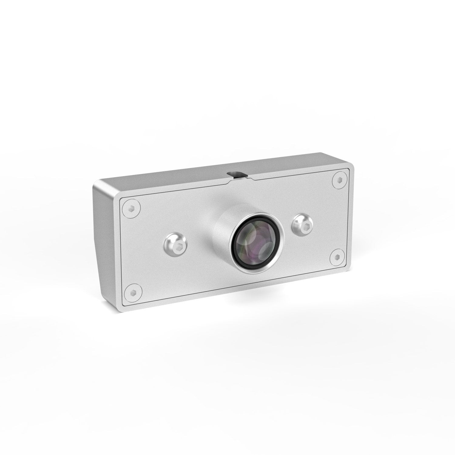
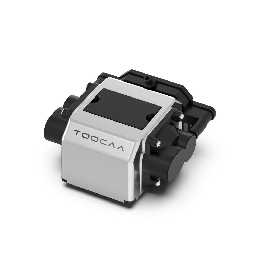
Step 3/32 Install the laser module.


Step 5/32 Connect the Type-C cable and lock the screws.

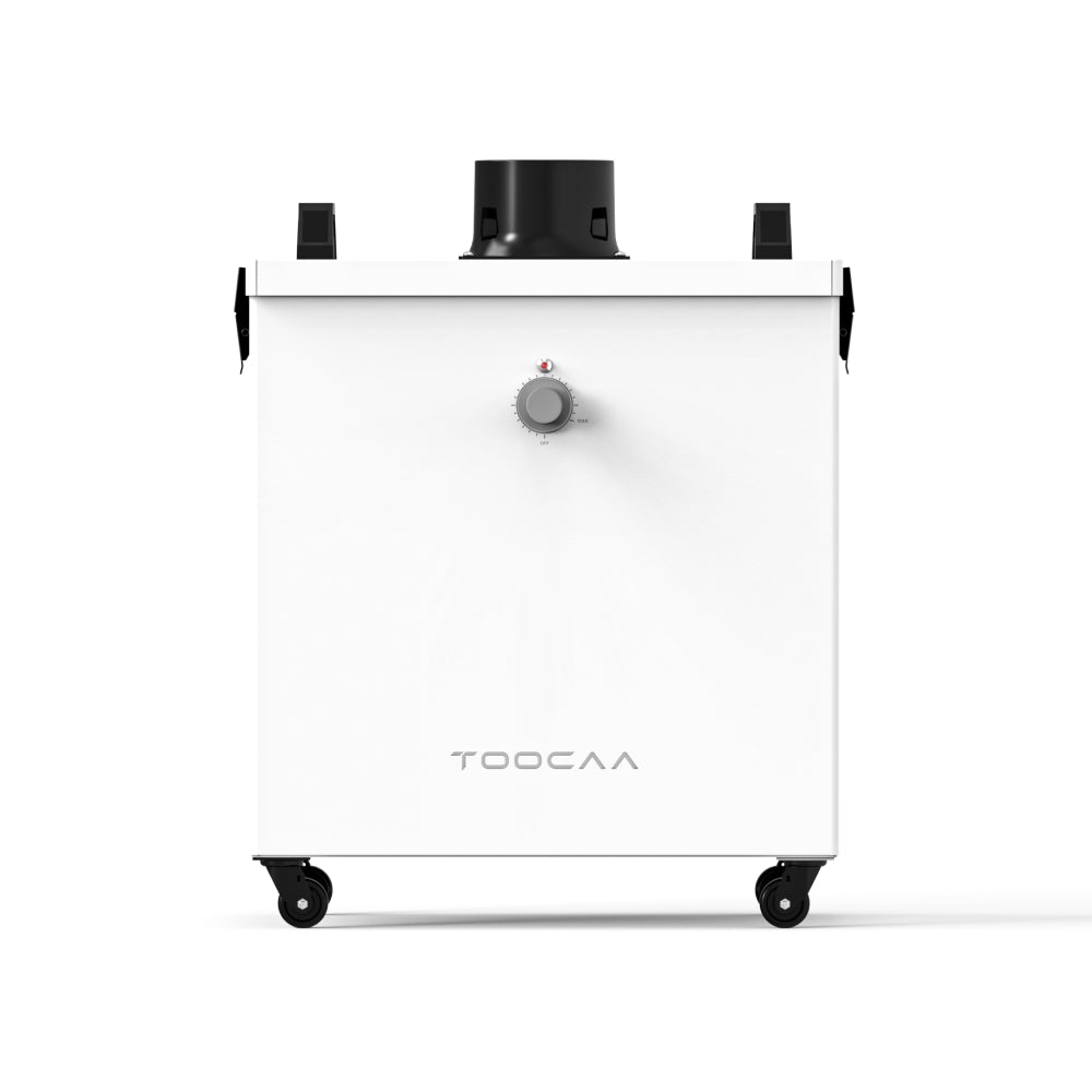
Step 6/32 Use M4*55 screws to assemble the exhaust system on the rear panel.


Step 8/32 Use M4*10 screws to lock the back panel and aluminum profile.

Step 9/32 Use M4*10 screws to secure the retaining part of the stop-at-will spring to the left and right panels.

Step 10/32 Fit both of left and right panels to the aluminum profile on the back panel.


Step 11/32 Use M4*10 screws to secure the left and right panels to the hardware connectors on the back panel.

Step 12/32 Connect the LED strips control cables.

Step 13/32 Mounting and securing profile for the top cover panel.


Step 14/32 Use M4*10 screws to mount profile of fixed top cover panel.

Step 15/32 Install the fixed top cover panel into the groove of the left/right panel against the rear end.

Step 16/32 Use M4*10 screws, mount the fixed top cover panel near the top position of the rear panel.

Step 17/32 Use M4*16 screws, fix the fixed top cover panel profiles to the left and right panels.


Step 19/32 Use M4*10 screws to lock the movable top cover panel and profile.

Step 20/32 Use M4*20 screws, attach the fixed structural parts of the nitrogen spring to the movable upper cover panel.


Step 21/32 Place the movable top cover panel onto the left and right panels.

Step 22/32 Place the movable top cover panel onto the left and right panels.

Step 23/32 Use M4*10 screws to assembly the front panel profile to the front panel.


Step 24/32 Use M4*10 screws to attach the handle to the front panel.

Step 25/32 Assemble the front panel profile to the movable top cover panel and lock it with M4*10 screws.


Step 26/32 Install the nitrogen springs to the left and right panels.


Step 27/32 Install the nitrogen spring onto the movable top cover panel.

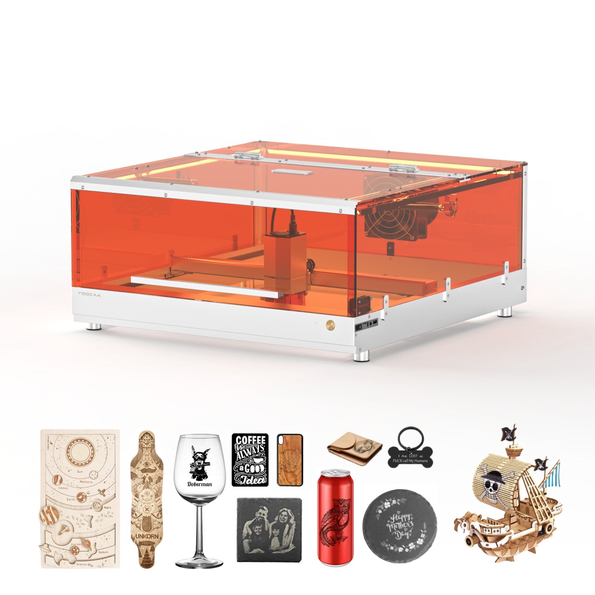
Step 28/32 Place the smart enclosure on the machine.

Step 29/32 Use M4*8 screws to attach the platen kit to fix the machine and smart enclosure.


Step 30/32 Connect the control wires of the LED strips.

Step 31/32 Use stainless steel clamps, mount the duct to the fan flange.

Step 32/32 Tighten the stainless-steel clamps.